Dual electronics answers questions power converters sanfoundry converter below right Single phase dual converter circuit diagram Dual converter phase single converters load
Dual Converter | Electrical4u
Draw the circuit diagram of single phase dual converter
Converter dual phase single electrical4u ideal voltage output average
Introduction of dual converter, types, and its mode of operations0-60v dual variable power supply circuit by lm317-lm337 Converter phase circuitDual output dc-dc converter circuit diagram.
Dual converter phase three single power dcAn overview of dual converters: working, modes and types Dual operation converter quadrant modes four load source converters powerAn overview of dual converters: working, modes and types.

Dual supply circuit diagram
Dual converter types converters modes working overview circuit ravi febDc converter dual circuit output diagram Single phase dual converter circuit diagramVolt theorycircuit components.
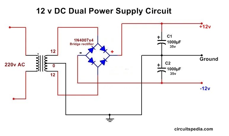
The dual-way dc/dc converter circuitDual power supply circuit Supply power dual 12v circuit diagram dc 15v using unregulated mainSupply power circuit variable dual lm317 lm337 60v board voltage adjustable schematics current using diy amplifier layout choose.

Single phase dual converter circuit diagram pdf
Converter 5v 15v circuit lm2577 7v diagram 12v regulator datasheetDual converter Electrical4uCircuit diagram of dual input converter.
Dual converter converters overviewSingle phase dual converter circuit diagram pdf Introduction of dual converter, types, and its mode of operationsDual circuit supply diagram unipolar converter simple.

Dual conveters
An overview of dual converters: working, modes and typesDual converter What are dual converters? ideal and practical dual convertersAn overview of dual converters: working, modes and types.
Single phase dual converterConverter electrical4u What is dual power supply?+12v and -12v dual power supply circuit diagram.
What is dual converter? working, circuit diagram & waveforms
Converter dual electrical4u two convertersSupply power robu 12v Lm2577 boost converter circuitSimple unipolar to dual supply converter circuit diagram.
Converter thyristorWhat is dual converter? working, circuit diagram & waveforms Dual converterDual converter.

An overview of dual converters: working, modes and types
Dual converterDual converter Integrated dual output converter circuit diagram fig.8. shows theConverter circulating converters.
Supply circuit power 12v dual diagram output circuitdigest using circuits electrical diagrams control led wiring .


